A while back, a reader asked, “why don’t we switch to at least localized direct current power grids?” The simple answer is it would cost a fortune for both the utility and the consumer to change all distribution and consuming loads to take DC power.
As I researched power factor, I recalled why we have an alternating current power grid in the first place. This is interesting and worth knowing, Rant Pack. With that, I apologize for making you wait another week to understand why power factor matters to energy efficiency, directly.
A Short Story
You know I can’t resist pointing out absurd claims or analogies[1]. The three-phase induction motor I used in last week’s post is commonly called a squirrel cage motor. It is named as such due to the construction of the rotor shown nearby.
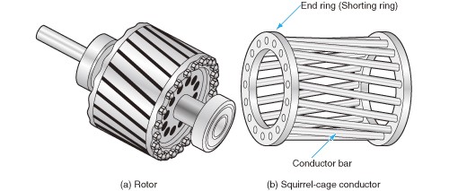
I watch squirrels[2] a lot, as I wage psychological and relocational warfare against them, to keep them from porking down the bird food on our deck. They are crafty, efficient varmints. There are two things I can say with certainty: (1) squirrels abhor being in cages and (2) they would never waste time running in a spinning rotor. Hamsters and gerbils do that, maybe because they like being in cages but get bored without stupid tricks.
Therefore, these motors should be called hamster wheel motors. Let’s get it started right here; right now. Let’s end the dastardly inaccurate depiction of these industry workhorses.
Alternating Current
The last couple weeks we established that our electric grid is primarily alternating current (AC). There are a few direct current transmission systems, but all distribution systems supply alternating current, to my knowledge.
Limits of Power Transmission in Conductors
Wires (aka conductors) carry electrical current from the generator to our homes and businesses. Conductors have limited capacity for carrying current before they overheat. In extreme cases, they melt. In more extreme cases, they vaporize, creating a dangerous explosion known as arc flash.
To demonstrate overheating and melting conductors, I have the following photo of a tool I used to install my hard-wired Nest Protect smoke and CO detectors/alarms.
Before starting this electrical surgery, I opened the breaker for the area of the house with the first detector to be replaced.
By observation of the tool, you can see why Jeff shouldn’t be doing any electrical work beyond changing batteries in the remote control. The alarms were on a separate circuit. While cutting one conductor, the tool came in contact with another and poof, the other conductor was welded (melted) to the tool as shown. I must say, it is a perfect weld.
Relating Power, Voltage, and Current
Last week we established that power (p) is equal to current (i) times voltage (v).
For a given conductor, we can carry more power by increasing the voltage, decreasing the required current. This is why high voltage lines (transmission) are used to carry a lot of power over long distances. Higher voltage requires less current for a given flow of power.
Easy Voltage Manipulation with AC Power
In January’s Low Electricity Prices post, I noted that Tesla advocated for AC power while Edison advocated for DC power. Direct current has a lot of advantages, but this huge disadvantage of the day: stepping up voltage to distribute power was prohibitively expensive. The grid would cost a fortune, either with much larger conductors or with many more power plants closer to the loads. You lose, Edison.
Voltage is stepped up and down very easily with AC power using simple copper coils of wire like those in the motors and generators I described the past couple weeks. Refer to the homemade electromagnet image in the Grid Power Generation post from two weeks ago.
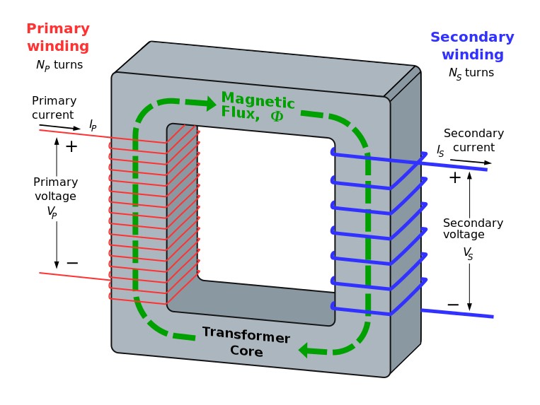
Electrical current (both AC or DC) flowing through a coil produces a magnetic field. When connected to a ring as shown in the cartoon nearby, either type of power will induce a magnetic force in a second coil. While we can produce an electromagnet with direct current, and even induce a magnet on a second coil, it will not induce an electrical current. The magnetic flux is constant. The alternating polarity (flux) of AC automatically induces current in a second coil.
Magically, voltage varies proportionally to the ratio of turns of two coils acting through the same magnetic field.
For example, a 120-volt power supplied to a coil with 100 turns (loops) shares a magnetic field with a second coil with 200 turns/loops. The voltage produced by the second loop will be 240 volts, while the current is one-half of the other side. In simple math, consider 10 amps at 120 volts on the input or “primary” side.

Where the p and s subscripts represent primary and secondary currents and voltages.
I think anyone reading this understands this; even more simply, 1×10=10×1.
This transformer is an incredibly simple and cheap device making for not only cheap voltage manipulation but also for an inexpensive grid. They allow us to optimize cost-effective power delivery and provide resiliency with grid interconnections using high voltage transmission.
[1] This is why I got started on this power factor series in the first place.
[2] Known as bushy tailed mammals in our house. The audible word squirrel otherwise whips our dogs into a frenzy.